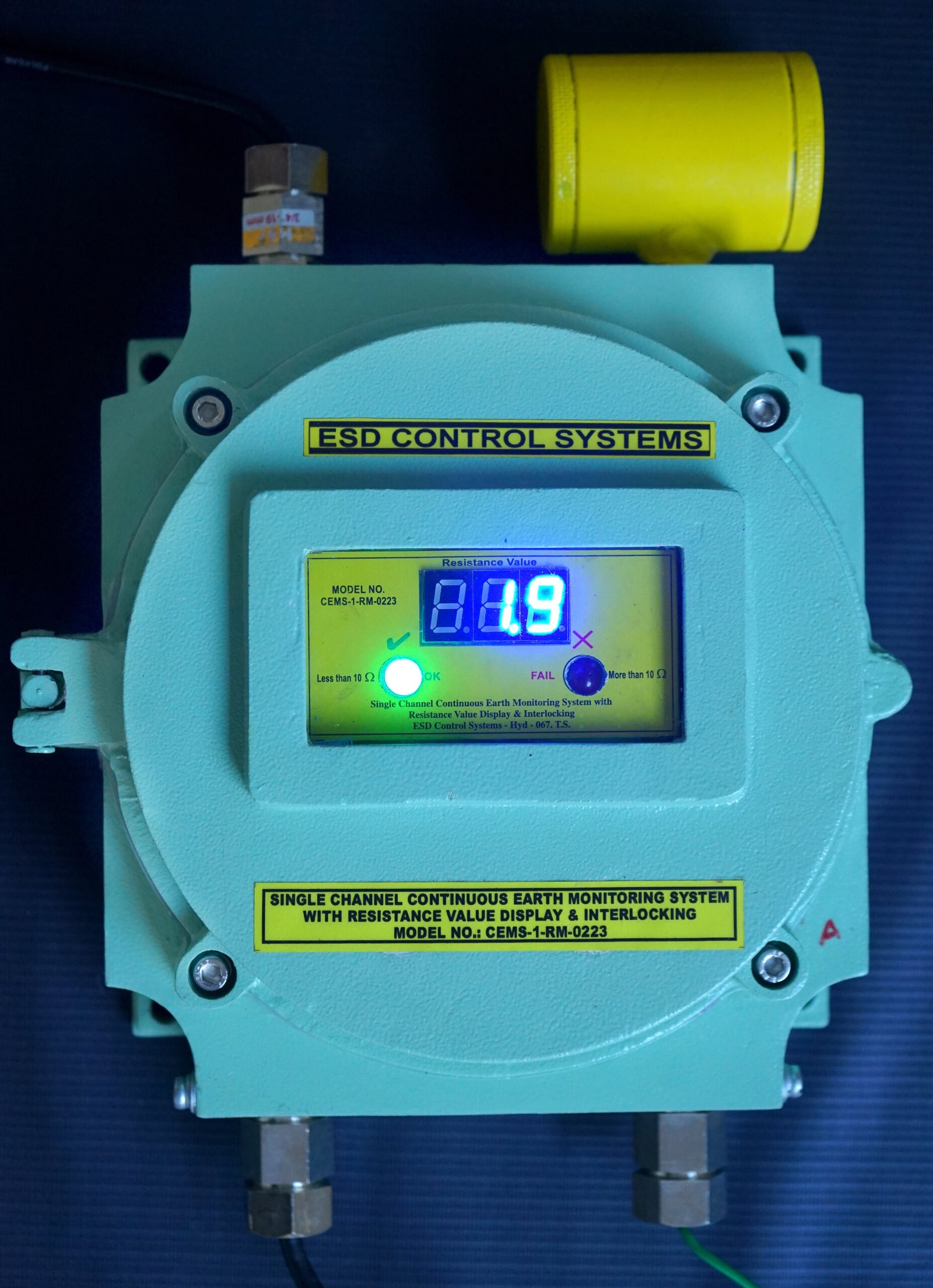
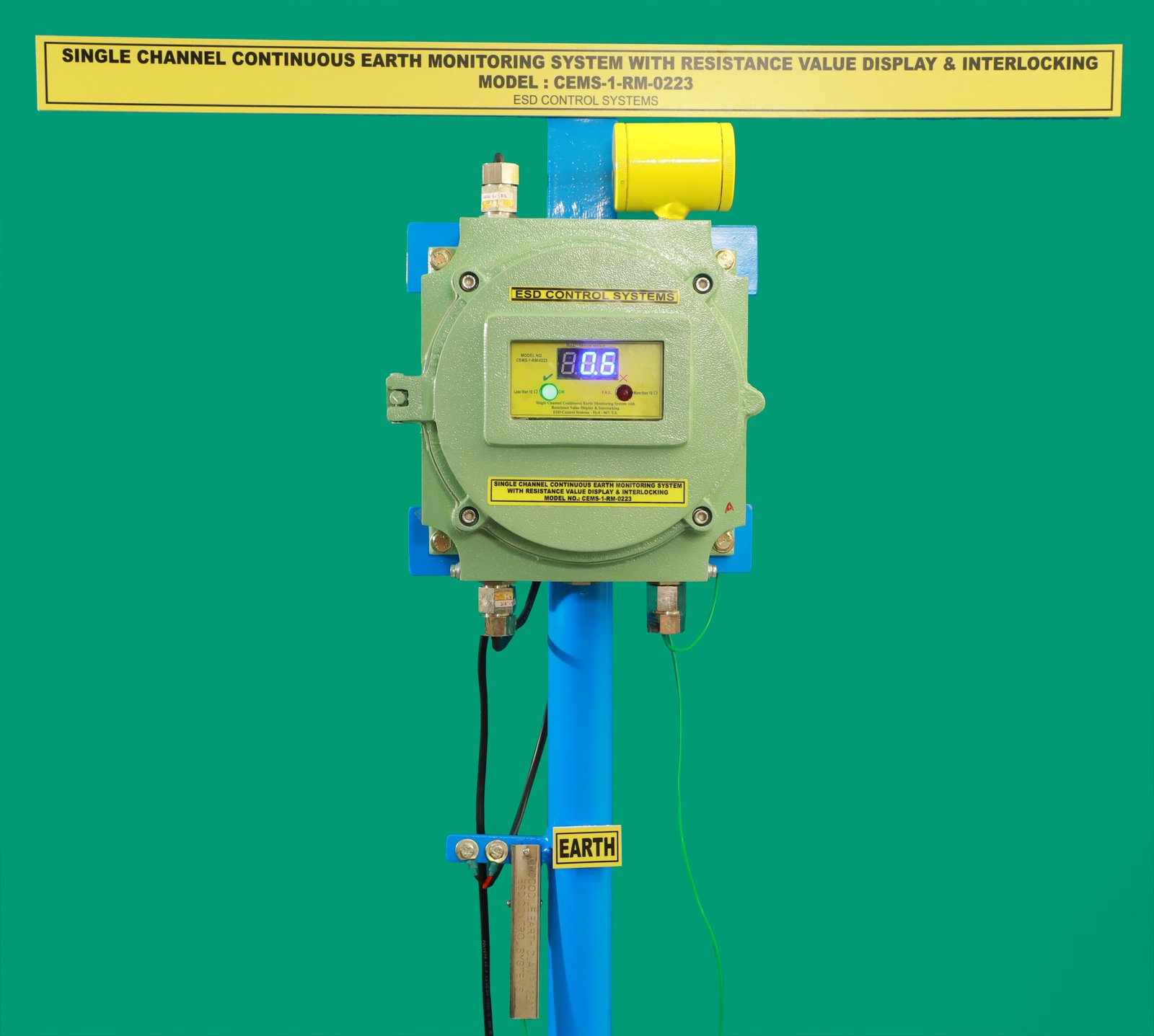
Model No.: CEMS-1-RM-0223
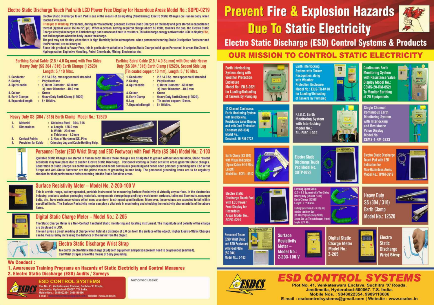
It is a well-known fact that friction created by any means will generate “Static Charges”. These charges if not dissipated to earth will result in Static Charges accumulation and subsequent Electro Static Discharge. The ESD may cause Fire and Explosions.
In Pharma & Chemical units, equipment such as Reactors, Centrifuges,Driers, Shifters, etc., are used continuously for 24 Hrs. in a day to manufacture different products. During the running of the above equipment, Static Charges are developed due to friction. All the equipment’s are to be earthed by means of earthing strips. Since equipment’s are running 24 hrs, the earth connections need to be healthy 24/7 to dissipate the Static Charges developed.
The duty of checking earth continuity of the equipment is normally assigned to the electrical department. Due to limited manpower in the department, monitoring earth connections on daily basis is not practicable. The Earth connections are usually checked once in 3 months or 6 months. Any loose contacts are defects in earth connections goes unnoticed during these intervals.
Why less than 10.0 Ohms threshold? As per IS/IEC 60079-0: 2017 &
IS/IEC 60079-11:2011 metallic items in good contact with the earth should have a resistance to it of less than 10.0 Ohms. Although a value of up to 1.0 M Ohms is acceptable for static dissipation values above 10.0 Ohms may give an early indication of developing problems (e.g. corrosion or loose connection).
Mr. P.V.Vidyadhara Rao (Proprietor) is an ESD Trainer and Certified ESD Auditor. During the ESD Audits, he noticed a safety gap in equipment earth connection monitoring and envisaged a need for a continuous earth monitoring system to fill this safety gap. Based on his findings and recommendations our Technical Team has designed and developed a continuous earth monitoring system CEMS-1-RM-0223 to fill the gap and reduce workload on electrical personnel, and continuity in the safety through the production schedule.
A key function of equipment Earthing is to provide a controlled method to prevent the buildup of static electricity, thus reducing the risk of electrical Discharge in Potentially hazardous environments. The Electrical resistance from the equipment to Earth should be 10.0 Ohms Maximum. This electrical resistance values are to be maintained continuously as per IS: 7689.
The system CEMS-1-RM-0223 monitors resistance value to Earth and any fault will be indicated by a RED LED and Audio Signal. The system monitors equipment connected continuously. The system draws the attention of the personnel to take remedial action should a fault arise in equipment earthing. (Red LED light up and Aural Bip sound together)
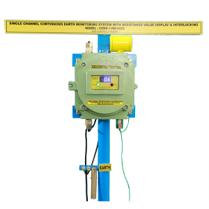
CEMS-1-RM-0223 has provision to monitor Single equipment, and comes in a flame-proof enclosure. Equipment to earth loop is measured by intrinsically safe voltage & current. Wiring details given in Schematic Block Diagram.
CEMS-1-RM-0223 is a Ex-Certified System as per
IS/IEC 60079-0 : 2017
IS/IEC 60079-11:2011
With Certificate No.: KLPL/Ex/16-014X-Issue No. 01, Dated: 30/03/2023
FLP Unit at Hazardous Area
1. ELECTRICAL SPECIFICATIONS:
Note: Earth monitoring clamp provided with 5.0 Mtrs. Cable intended to be clamped on to unloading metal container. Container will have its existing earthing clamp.
2. MECHANICAL SPECIFICATIONS:
Main Console: FLP Enclosure 220 x 220 mm, Window 100 x 50 mm glass Window. Flame proof and Weather proof as per IP 65. Aluminium Alloy LM Casting – 5.30 Kgs. (approx.) Approved Certified Item.
3. ENVIRONMENTAL:
Operating Temperature Range: – 100 to 500 .
Material requirement for Installation of CEMS-1-RM-0223
Your Scope of Work & Supply
Caution Note:
Before carrying out any electrical welding works on connected Equipment structures and periferrals during maintenance activities.
Because CEMS-1-RM-0223 unit printed circuit remains connected to earth pit, even if power is switch OFF to unit, branched out welding currents flows through E. loop sensing lead through narrow printed cirucit strips to earth pit, it damges the printed circuit board.
To prevent above damage, remove the two 4 Sq.mm cable coming from earth pit to terminal block in junction box. Remove the two wires, tape the open ends and lay it in free space in junction box. Other earth loop check wires (1.5 Sq.mm wires) are also to be remvoed from their terminals and pulled out of respective glands and hold out side the junction box. Before putting back in service CEMS-1-RM-0223 restore all the 1.5 Sq.mm E. loop wires in their sequence and restore the earth pit wires.
In reference to system block diagram connection, details for cable connections are as under.
Hazardous Area : FLP Unit
Cable Entry-1: 1.5 Sq.mm 3 core copper flexible Armored cable.
1st Connection: Mains Supply Point,
2nd Connection: FLP Unit End
Continuous Earth Monitoring System is designed to Monitor Earthing of Pharma product process equipment. Once installed the system checks single monitoring point.
In the event of equipment earthing fault (resistance more than 10 Ohms), the system detects it and indicates Red color LED along with Audio Signal. At the same time.
This data is provided for general information and material comparison. The potential user should perform tests to determine the product’s performance and suitability in the intended application. Final determination of the fitness of the product for any particular application is the responsibility of the buyer.
It is a well-known fact that friction created by any means will generate “Static Charges”. These charges if not dissipated to earth will result in Static Charges accumulation and subsequent Electro Static Discharge. The ESD may cause Fire and Explosions.
In Pharma & Chemical units, equipment such as Reactors, Centrifuges,Driers, Shifters, etc., are used continuously for 24 Hrs. in a day to manufacture different products. During the running of the above equipment, Static Charges are developed due to friction. All the equipment’s are to be earthed by means of earthing strips. Since equipment’s are running 24 hrs, the earth connections need to be healthy 24/7 to dissipate the Static Charges developed.
The duty of checking earth continuity of the equipment is normally assigned to the electrical department. Due to limited manpower in the department, monitoring earth connections on daily basis is not practicable. The Earth connections are usually checked once in 3 months or 6 months. Any loose contacts are defects in earth connections goes unnoticed during these intervals.
Why less than 10.0 Ohms threshold? As per IS/IEC 60079-0: 2017 &
IS/IEC 60079-11:2011 metallic items in good contact with the earth should have a resistance to it of less than 10.0 Ohms. Although a value of up to 1.0 M Ohms is acceptable for static dissipation values above 10.0 Ohms may give an early indication of developing problems (e.g. corrosion or loose connection).
Mr. P.V.Vidyadhara Rao (Proprietor) is an ESD Trainer and Certified ESD Auditor. During the ESD Audits, he noticed a safety gap in equipment earth connection monitoring and envisaged a need for a continuous earth monitoring system to fill this safety gap. Based on his findings and recommendations our Technical Team has designed and developed a continuous earth monitoring system CEMS-1-RM-0223 to fill the gap and reduce workload on electrical personnel, and continuity in the safety through the production schedule.
A key function of equipment Earthing is to provide a controlled method to prevent the buildup of static electricity, thus reducing the risk of electrical Discharge in Potentially hazardous environments. The Electrical resistance from the equipment to Earth should be 10.0 Ohms Maximum. This electrical resistance values are to be maintained continuously as per IS: 7689.
The system CEMS-1-RM-0223 monitors resistance value to Earth and any fault will be indicated by a RED LED and Audio Signal. The system monitors equipment connected continuously. The system draws the attention of the personnel to take remedial action should a fault arise in equipment earthing. (Red LED light up and Aural Bip sound together)
CEMS-1-RM-0223 has provision to monitor Single equipment, and comes in a flame-proof enclosure. Equipment to earth loop is measured by intrinsically safe voltage & current. Wiring details given in Schematic Block Diagram.
CEMS-1-RM-0223 is a Ex-Certified System as per
IS/IEC 60079-0 : 2017
IS/IEC 60079-11:2011
With Certificate No.: KLPL/Ex/16-014X-Issue No. 01, Dated: 30/03/2023
FLP Unit at Hazardous Area
1. ELECTRICAL SPECIFICATIONS:
Note: Earth monitoring clamp provided with 5.0 Mtrs. Cable intended to be clamped on to unloading metal container. Container will have its existing earthing clamp.
2. MECHANICAL SPECIFICATIONS:
Main Console: FLP Enclosure 220 x 220 mm, Window 100 x 50 mm glass Window. Flame proof and Weather proof as per IP 65. Aluminium Alloy LM Casting – 5.30 Kgs. (approx.) Approved Certified Item.
3. ENVIRONMENTAL:
Operating Temperature Range: – 100 to 500 .
Caution Note:
Before carrying out any electrical welding works on connected Equipment structures and periferrals during maintenance activities.
Because CEMS-1-RM-0223 unit printed circuit remains connected to earth pit, even if power is switch OFF to unit, branched out welding currents flows through E. loop sensing lead through narrow printed cirucit strips to earth pit, it damges the printed circuit board.
To prevent above damage, remove the two 4 Sq.mm cable coming from earth pit to terminal block in junction box. Remove the two wires, tape the open ends and lay it in free space in junction box. Other earth loop check wires (1.5 Sq.mm wires) are also to be remvoed from their terminals and pulled out of respective glands and hold out side the junction box. Before putting back in service CEMS-1-RM-0223 restore all the 1.5 Sq.mm E. loop wires in their sequence and restore the earth pit wires.
Start-end connections as follows.
1) Red 12 V DC.
2) Black 0 V.
3) Yellow Interlock Control 12 V.
4) Blue 0 V.
230 Volts input. Use 1mm² 2 Core/3core PVC cable taking supply from main panel
Electrical Specification: –
4 mm threaded hole provided on each side top extended strip. Use it for electrical grounding.
Pump Motor Control line 230 Volts Interlock control wires termination on 1 to 10 terminal blocks.
These control wires originate from built in contactor. This provides 230 V link connection for control points of respective pump motors.
The existing control feed wire (230 Volts) to be replaced with one of the wires from control points.
Measure and enter
Bottom door
No. of cable entries on FLP unit: 3 Nos.
This wire end is to be connected to earth pit connection point of G.I. strips.
WARNING: Ensure that the electrical installation conforms with your local and national safety requirements. It must be connected to a suitably fused and protected electrical supply and a suitable electrical earth point.
In reference to system block diagram connection, details for cable connections are as under.
Hazardous Area : FLP Unit
Cable Entry-1: 1.5 Sq.mm 3 core copper flexible Armored cable.
1st Connection: Mains Supply Point,
2nd Connection: FLP Unit End
Continuous Earth Monitoring System is designed to Monitor Earthing of Pharma product process equipment. Once installed the system checks single monitoring point.
In the event of equipment earthing fault (resistance more than 10 Ohms), the system detects it and indicates Red color LED along with Audio Signal. At the same time.
It is a well-known fact that friction created by any means will generate “Static Charges”. These charges if not dissipated to earth will result in Static Charges accumulation and subsequent Electro Static Discharge. The ESD may cause Fire and Explosions.
In Pharma & Chemical units, equipment such as Reactors, Centrifuges,Driers, Shifters, etc., are used continuously for 24 Hrs. in a day to manufacture different products. During the running of the above equipment, Static Charges are developed due to friction. All the equipment’s are to be earthed by means of earthing strips. Since equipment’s are running 24 hrs, the earth connections need to be healthy 24/7 to dissipate the Static Charges developed.
The duty of checking earth continuity of the equipment is normally assigned to the electrical department. Due to limited manpower in the department, monitoring earth connections on daily basis is not practicable. The Earth connections are usually checked once in 3 months or 6 months. Any loose contacts are defects in earth connections goes unnoticed during these intervals.
Why less than 10.0 Ohms threshold? As per IS/IEC 60079-0: 2017 &
IS/IEC 60079-11:2011 metallic items in good contact with the earth should have a resistance to it of less than 10.0 Ohms. Although a value of up to 1.0 M Ohms is acceptable for static dissipation values above 10.0 Ohms may give an early indication of developing problems (e.g. corrosion or loose connection).
Mr. P.V.Vidyadhara Rao (Proprietor) is an ESD Trainer and Certified ESD Auditor. During the ESD Audits, he noticed a safety gap in equipment earth connection monitoring and envisaged a need for a continuous earth monitoring system to fill this safety gap. Based on his findings and recommendations our Technical Team has designed and developed a continuous earth monitoring system CEMS-1-RM-0223 to fill the gap and reduce workload on electrical personnel, and continuity in the safety through the production schedule.
A key function of equipment Earthing is to provide a controlled method to prevent the buildup of static electricity, thus reducing the risk of electrical Discharge in Potentially hazardous environments. The Electrical resistance from the equipment to Earth should be 10.0 Ohms Maximum. This electrical resistance values are to be maintained continuously as per IS: 7689.
The system CEMS-1-RM-0223 monitors resistance value to Earth and any fault will be indicated by a RED LED and Audio Signal. The system monitors equipment connected continuously. The system draws the attention of the personnel to take remedial action should a fault arise in equipment earthing. (Red LED light up and Aural Bip sound together)
CEMS-1-RM-0223 has provision to monitor Single equipment, and comes in a flame-proof enclosure. Equipment to earth loop is measured by intrinsically safe voltage & current. Wiring details given in Schematic Block Diagram.
CEMS-1-RM-0223 is a Ex-Certified System as per
IS/IEC 60079-0 : 2017
IS/IEC 60079-11:2011
With Certificate No.: KLPL/Ex/16-014X-Issue No. 01, Dated: 30/03/2023
FLP Unit at Hazardous Area
1. ELECTRICAL SPECIFICATIONS:
6. Intrinsically Safe Outputs: 1 Line to Equipment for Earth Loop Check and inputs 2 lines to Earth Pits.
7. Enclosure: FLP (Zone-1)
8. Mounting: Wall mounting by four M8 x 25 screws On extended fixtures.
Material requirement for Installation of CEMS-1-RM-0223
Your Scope of Work & Supply
2. The equipment earthing is to be thoroughly checked and a report on existing resistance values of equipment to Earth Pit to be furnished to us prior to installation.
3. 1.5 Sq.mm copper flexible 3 cores Armored is to be provided from Mains supply point.
4. 1.5 Sq.mm 4 Cores PVC cable from FLP Unit to Earth Pits or verified earth plate point to be provided.
Caution Note:
Before carrying out any electrical welding works on connected Equipment structures and periferrals during maintenance activities.
Because CEMS-1-RM-0223 unit printed circuit remains connected to earth pit, even if power is switch OFF to unit, branched out welding currents flows through E. loop sensing lead through narrow printed cirucit strips to earth pit, it damges the printed circuit board.
To prevent above damage, remove the two 4 Sq.mm cable coming from earth pit to terminal block in junction box. Remove the two wires, tape the open ends and lay it in free space in junction box. Other earth loop check wires (1.5 Sq.mm wires) are also to be remvoed from their terminals and pulled out of respective glands and hold out side the junction box. Before putting back in service CEMS-1-RM-0223 restore all the 1.5 Sq.mm E. loop wires in their sequence and restore the earth pit wires.
In reference to system block diagram connection, details for cable connections are as under.
Hazardous Area : FLP Unit
Cable Entry-1: 1.5 Sq.mm 3 core copper flexible Armored cable.
1st Connection: Mains Supply Point,
2nd Connection: FLP Unit End
Continuous Earth Monitoring System is designed to Monitor Earthing of Pharma product process equipment. Once installed the system checks single monitoring point.
In the event of equipment earthing fault (resistance more than 10 Ohms), the system detects it and indicates Red color LED along with Audio Signal. At the same time.
ESD Control Systems is a leader in certified advanced ESD product solutions and offers safety audit services, accident investigations, learning, and Training Programs – catering to the Pharmaceutical, Chemical, Defense, and Space and Electronics industries. ESD Control Systems’ Mission is to be the Static Dissipation Solution Provider for the World
ESD Control Systems is a leader in certified advanced ESD product solutions and offers safety audit services, accident investigations, learning, and Training Programs – catering to the Pharmaceutical, Chemical, Defense, and Space and Electronics industries. ESD Control Systems’ Mission is to be the Static Dissipation Solution Provider for the World
WhatsApp us