Model No.: Decalock-10-RM-0722
Static Electricity is an imbalance of electric charges within or on the surface of a material. It is a well-known fact that when two surfaces contact and separate, static charges are generated. The charge remains until it can move away using an electric current or electrical discharge. When flammable or combustible atmospheres are present, uncontrolled discharges of static electricity are potentially dangerous or even catastrophic. Statistics from worldwide safety institutions show that there are at least two major industrial accidents daily, caused by uncontrolled electro static discharge inflammable or combustible locations.
In Pharma & Chemical industries to get the final product equipment like FBDs, millers, micronizers, sifters, blenders, etc., are used typically in clean rooms. Since most of the equipment or some parts of the equipment like FBD bowls are mobile, it is not possible to provide a permanent earth connection to the equipment. Hence temporary earth connection is to be provided using crocodile earth clamps.
During the process, if there is any failure in the earth connection, the equipment Should automatically stop to avoid static charge generation. The shutting down of the process or the continuous measurement of earth connection by personnel is neither an economical nor an efficient option. This gave roots to the idea of DECALOCK-10-RM-0722.
INTRODUCTION
The resistance value for any grounding connection, as per, IS : 7689 should be less than 10 Ohms. 10 Channels scans the equipment’s earthing connection for all the 10 Channels. Earth fault (more than 10 Ω) will be indicated by RED LED registration provided on the main unit along with shutting down the respective equipment. The system monitors every equipment with an interval of 5 seconds.
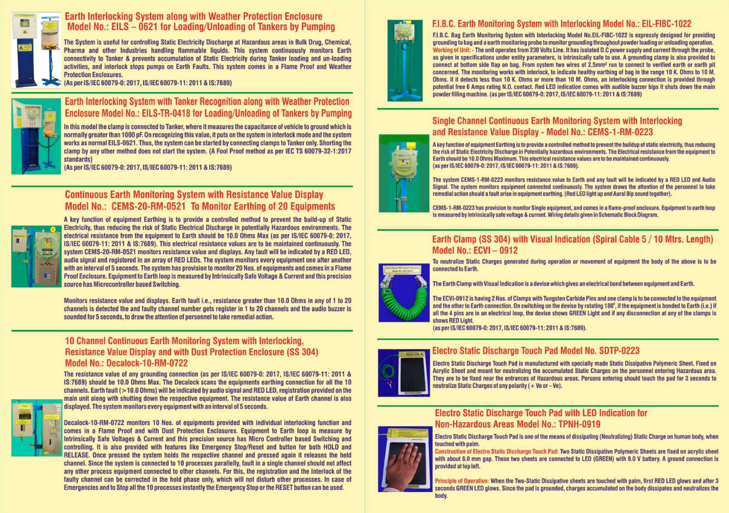
DECALOCK–10-RM-0722 monitors 10 Nos. of equipments provided with individual interlocking functions and comes in a flame-proof enclosure. Equipment to earth loop is measured by intrinsically safe voltage & current and this precisions source has microcontroller-based switching and controlling. It is also provided with features like emergency stop/RESET and a dual functioning button for both HOLD and RELEASE. Once pressed the system holds the respective channel and pressed again it releases the held channel. Since the system is connected to 10 processes parallelly, fault in a single channel should not affect any other process equipment connected to other channels. For this, the registration and the interlock of the faulty channel can be corrected in the hold position only, which will not disturb other processes. In case of emergencies and to stop all the 10 processes at an instant the emergency stop or the RESET button can be used.
It is a Ex Safety certified instrument bearing certification Nos.: KLPL/Ex/19-015X, KLPL/Ex/19-016X, Issue No. 01, Dated: 30/03/2023
ELECTRICAL SPECIFICATIONS:
1 Power Input: 12V DC through wires 1 & 2, 4 Core Cable
2. Load: 5 Watts.
3. Interlock: 10-Channels
4. Cable Entries: As given in System Block Diagram
5. Operational Switches:
6. Operational Indications:
7. Intrinsically safe Outputs: 1 – 10- Lines to Equipment for Earth Loop Check and inputs 2 lines from Earth Pits.
8. Enclosure: FLP (Zone-1) – IP-66
Interlock and reset provided through data and rest line of the two-wire other than 12 Volts supply in 4 core cable as given in block diagram.
9.Mounting: Wall mounting by four M8 x 25 screws on extended fixtures.
MECHANICAL SPECIFICATIONS:
1 Dimensions: 500 x 300 x 155mm
2. Material: S.S. box.
3. Weight: 10.0 Kgs.
III. ENVIRONMENTAL:
Operating Temperature Range: – 100 to 50O
Safe Area Unit: Located in safe area (Switch Gear Room)
I. ELECTRICAL SPECIFICATIONS:
1. Power Input: 230V ~(AC Mains)
2. Total Load: Approx 15 Watts. 9 Watts Safe area + 5 Watts FLP
Unit for Total System
3. Interlock: 10-Channels
4. Cable Entries: As given in System Block Diagr
5. Relay Type: Potential free N.O. Contacts with 6 Amps rating.
Operational Indications: 10 Channels Interlock relay status
indicated by 5 mm Green and Red LEDs (Relay ON/OFF)
Located respective relay marked 1 to 10, viewed through window on Safe Area unit top cover
7. Outputs/Inputs Connections: Through 1.5 mm Square 4 Core Armoured Cable Connections.
8. Enclosure: Non- FLP MS Box (Safe Area Unit)
9.Mounting: Wall Mounting by Four M8 x 25 Screws on extended fixtures.
MECHANICAL SPECIFICATIONS:
1) Dimensions: 330 x 330 x 90 mm
2) Material: M.S. Powder coated.
3) Weight: 6.0 Kgs.
III. ENVIRONMENTAL:
Operating Temperature Ranges: -100 to 500
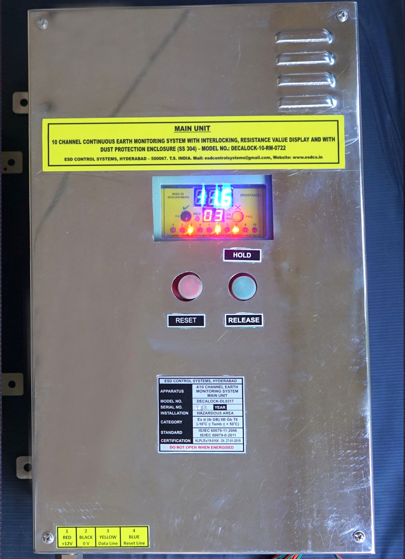
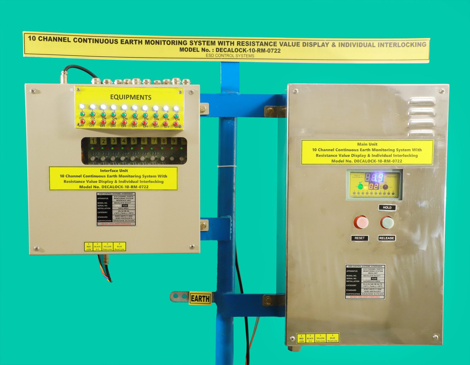
Decalock is specifically designed to monitor equipment’s earthing connection with the feasibility of stalling the equipment in case of a fault in the earth loop. The system consists of two separate units namely Main Unit and Interface Unit. The Main Unit continuously monitors 10 channels with a 5-seconds interval. The main unit communicates with the Interface Unit which is provided with an individual interlock for all the. 10 channels. When any channels earth loop resistance is more than 10 Ohms or faulty, the main unit communicates with the interface unit which engages or disengages the interlock, stalling the respective equipment until checked and corrected. Hence the name DECALOCK-10-RM-0722.
The main unit and interface unit have LED indication facility to determine which channel is/was faulty and what is the state of any relay at any given time respectively. The main unit is an S.S box consisting of a flame proof enclosure with a display window and two push buttons along with a 10+2 way terminal block for connections (Please refer to the block diagram). The layout of the display in the window of the FLP enclosure consists of 1 No. of 10 mm RED colored LED display, 1 No. Of GREEN colored LED display, 1No. YELLOW LED, 10 Nos. of RED LEDs. The red and yellow displays show the channels earth loop status. It shows from ‘01’ to ‘10’ channels.
The YELLOW LED is provided to indicate HOLD function and the 10 Nos. of RED LEDs are for indicating the registration of faulty channels. The two buttons on the equipment helps the user to interact with the system. The RED coloured button on the left is for RESET. This RESET functionality is for emergencies or to shut down all the equipment connected to the 10 Channels.
When a channel is registered faulty with the RED LED registration, the user can hold the respective channel by pressing the Green button and check for any faults in grounding and correct them. After correction, the RED LED registration disappears for that channel and the user can press the Green button again for the system to continue with the scanning. The 10 Nos. Of RED LED registration can be checked at any time until resetted.
Maintenance
Indication | Cause | Trouble Shooting |
Resistance Measurement Channel Display in BLUE 7 – Segment. Channel Display in Yellow 7-Segment Red LEDs registration on 1 to 10 Channels. | Earthing of the Channel is faulty in respect of registered LEDs | Hold the Channel and check for discontinuity in earthing connection. |
Process equipment connected to DECALOCK does not turn ON Due to interlock | Earthing of the equipments is faulty | Check for fault LED registration. If RED check the earthing. If not RED check for a faulty relay or contact manufacturer. |
No display on main unit but interface relay board indications are O.K. | Defective 12 V Power Supply | Check for a burnt fuse in the interface unit on 12V power supply PCB. |
No display on interface relay board unit but main unit is O.K. | Defective 12 V ‘B’ Power Supply. there is a separate 12V Power Supply for relay circuit. | Check for a burnt fuse in the interface unit on 12V power supply PCB. |
No display on both the units. | Total power supply defective. | Check for burnt fuses, check if the power supply to the interface unit is ON. |
Note: 2 Nos. Of 250ma fuses in AC Power Supply input PCB.
1 No. Of 250ma fuse in 12V DC Power Supply PCB.
1 No. Of 0.5 A in 12 V DC Power Supply PCB.
Contact Manufacturer in case of any other faults which are not mentioned above. Do not open the main unit without the manufacture’s consent. Any changes to the system without the manufacturer’s consent will void the Warranty.
Your scope of work & supply
ESD Control Systems
This data is provided for general information and material comparison. The potential user should perform tests to determine the product’s performance and suitability in the intended application. Final determination of the fitness of the product for any particular application is the responsibility of the buyer.
Static Electricity is an imbalance of electric charges within or on the surface of a material. It is a well-known fact that when two surfaces contact and separate, static charges are generated. The charge remains until it can move away using an electric current or electrical discharge. When flammable or combustible atmospheres are present, uncontrolled discharges of static electricity are potentially dangerous or even catastrophic. Statistics from worldwide safety institutions show that there are at least two major industrial accidents daily, caused by uncontrolled electro static discharge inflammable or combustible locations.
In Pharma & Chemical industries to get the final product equipment like FBDs, millers, micronizers, sifters, blenders, etc., are used typically in clean rooms. Since most of the equipment or some parts of the equipment like FBD bowls are mobile, it is not possible to provide a permanent earth connection to the equipment. Hence temporary earth connection is to be provided using crocodile earth clamps.
During the process, if there is any failure in the earth connection, the equipment Should automatically stop to avoid static charge generation. The shutting down of the process or the continuous measurement of earth connection by personnel is neither an economical nor an efficient option. This gave roots to the idea of DECALOCK-10-RM-0722.
INTRODUCTION
The resistance value for any grounding connection, as per, IS : 7689 should be less than 10 Ohms. 10 Channels scans the equipment’s earthing connection for all the 10 Channels. Earth fault (more than 10 Ω) will be indicated by RED LED registration provided on the main unit along with shutting down the respective equipment. The system monitors every equipment with an interval of 5 seconds.
DECALOCK–10-RM-0722 monitors 10 Nos. of equipments provided with individual interlocking functions and comes in a flame-proof enclosure. Equipment to earth loop is measured by intrinsically safe voltage & current and this precisions source has microcontroller-based switching and controlling. It is also provided with features like emergency stop/RESET and a dual functioning button for both HOLD and RELEASE. Once pressed the system holds the respective channel and pressed again it releases the held channel. Since the system is connected to 10 processes parallelly, fault in a single channel should not affect any other process equipment connected to other channels. For this, the registration and the interlock of the faulty channel can be corrected in the hold position only, which will not disturb other processes. In case of emergencies and to stop all the 10 processes at an instant the emergency stop or the RESET button can be used.
It is a Ex Safety certified instrument bearing certification Nos.: KLPL/Ex/19-015X,KLPL/Ex/19-016X
ELECTRICAL SPECIFICATIONS:
1 Power Input: 12V DC through wires 1 & 2, 4 Core Cable
2. Load: 5 Watts.
3. Interlock: 10-Channels
4. Cable Entries: As given in System Block Diagram
5. Operational Switches:
6. Operational Indications:
7. Intrinsically safe Outputs: 1 – 10- Lines to Equipment for Earth Loop Check and inputs 2 lines from Earth Pits.
8. Enclosure: FLP (Zone-1) – IP-66
Interlock and reset provided through data and rest line of the two-wire other than 12 Volts supply in 4 core cable as given in block diagram.
9.Mounting: Wall mounting by four M8 x 25 screws on extended fixtures.
MECHANICAL SPECIFICATIONS:
1 Dimensions: 500 x 300 x 155mm
2. Material: S.S. box.
3. Weight: 10.0 Kgs.
III. ENVIRONMENTAL:
Operating Temperature Range: – 100 to 50O
Safe Area Unit: Located in safe area (Switch Gear Room)
I. ELECTRICAL SPECIFICATIONS:
1. Power Input: 230V ~(AC Mains)
2. Total Load: Approx 15 Watts. 9 Watts Safe area + 5 Watts FLP
Unit for Total System
3. Interlock: 10-Channels
4. Cable Entries: As given in System Block Diagr
5. Relay Type: Potential free N.O. Contacts with 6 Amps rating.
Operational Indications: 10 Channels Interlock relay status
indicated by 5 mm Green and Red LEDs (Relay ON/OFF)
Located respective relay marked 1 to 10, viewed through window on Safe Area unit top cover
7. Outputs/Inputs Connections: Through 1.5 mm Square 4 Core Armoured Cable Connections.
8. Enclosure: Non- FLP MS Box (Safe Area Unit)
9.Mounting: Wall Mounting by Four M8 x 25 Screws on extended fixtures.
MECHANICAL SPECIFICATIONS:
1) Dimensions: 330 x 330 x 90 mm
2) Material: M.S. Powder coated.
3) Weight: 6.0 Kgs.
III. ENVIRONMENTAL:
Operating Temperature Ranges: -100 to 500
Decalock is specifically designed to monitor equipment’s earthing connection with the feasibility of stalling the equipment in case of a fault in the earth loop. The system consists of two separate units namely Main Unit and Interface Unit. The Main Unit continuously monitors 10 channels with a 5-seconds interval. The main unit communicates with the Interface Unit which is provided with an individual interlock for all the. 10 channels. When any channels earth loop resistance is more than 10 Ohms or faulty, the main unit communicates with the interface unit which engages or disengages the interlock, stalling the respective equipment until checked and corrected. Hence the name DECALOCK-10-RM-0722.
The main unit and interface unit have LED indication facility to determine which channel is/was faulty and what is the state of any relay at any given time respectively. The main unit is an S.S box consisting of a flame proof enclosure with a display window and two push buttons along with a 10+2 way terminal block for connections (Please refer to the block diagram). The layout of the display in the window of the FLP enclosure consists of 1 No. of 10 mm RED colored LED display, 1 No. Of GREEN colored LED display, 1No. YELLOW LED, 10 Nos. of RED LEDs. The red and yellow displays show the channels earth loop status. It shows from ‘01’ to ‘10’ channels.
The YELLOW LED is provided to indicate HOLD function and the 10 Nos. of RED LEDs are for indicating the registration of faulty channels. The two buttons on the equipment helps the user to interact with the system. The RED coloured button on the left is for RESET. This RESET functionality is for emergencies or to shut down all the equipment connected to the 10 Channels.
When a channel is registered faulty with the RED LED registration, the user can hold the respective channel by pressing the Green button and check for any faults in grounding and correct them. After correction, the RED LED registration disappears for that channel and the user can press the Green button again for the system to continue with the scanning. The 10 Nos. Of RED LED registration can be checked at any time until resetted.
Maintenance
Indication | Cause | Trouble Shooting |
Resistance Measurement Channel Display in BLUE 7 – Segment. Channel Display in Yellow 7-Segment Red LEDs registration on 1 to 10 Channels. | Earthing of the Channel is faulty in respect of registered LEDs | Hold the Channel and check for discontinuity in earthing connection. |
Process equipment connected to DECALOCK does not turn ON Due to interlock | Earthing of the equipments is faulty | Check for fault LED registration. If RED check the earthing. If not RED check for a faulty relay or contact manufacturer. |
No display on main unit but interface relay board indications are O.K. | Defective 12 V Power Supply | Check for a burnt fuse in the interface unit on 12V power supply PCB. |
No display on interface relay board unit but main unit is O.K. | Defective 12 V ‘B’ Power Supply. there is a separate 12V Power Supply for relay circuit. | Check for a burnt fuse in the interface unit on 12V power supply PCB. |
No display on both the units. | Total power supply defective. | Check for burnt fuses, check if the power supply to the interface unit is ON. |
Note: 2 Nos. Of 250ma fuses in AC Power Supply input PCB.
1 No. Of 250ma fuse in 12V DC Power Supply PCB.
1 No. Of 0.5 A in 12 V DC Power Supply PCB.
Contact Manufacturer in case of any other faults which are not mentioned above. Do not open the main unit without the manufacture’s consent. Any changes to the system without the manufacturer’s consent will void the Warranty.
Your scope of work & supply
ESD Control Systems
ESD Control Systems is a leader in certified advanced ESD product solutions and offers safety audit services, accident investigations, learning, and Training Programs – catering to the Pharmaceutical, Chemical, Defense, and Space and Electronics industries. ESD Control Systems’ Mission is to be the Static Dissipation Solution Provider for the World
ESD Control Systems is a leader in certified advanced ESD product solutions and offers safety audit services, accident investigations, learning, and Training Programs – catering to the Pharmaceutical, Chemical, Defense, and Space and Electronics industries. ESD Control Systems’ Mission is to be the Static Dissipation Solution Provider for the World
WhatsApp us

